
Obstacle Avoiding Car
Autonomous car using ultrasonic sensors and Arduino to navigate safely and avoid obstacles.
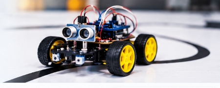
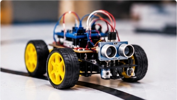

Project Overview
The Line Following Robot is designed to automatically follow a black line on a white surface. It uses infrared (IR) sensors to detect the line and a microcontroller (Arduino) to control the motors. This project is a great way for students to learn about robotics, sensors, and programming in a fun and practical way.
Project Features
- Automatically follows a black line
- Uses IR sensors for line detection
- Controlled by Arduino microcontroller
- Simple and cost-effective design
- Suitable for school and college level projects
Project Information
Detailed Explanation
The robot uses two IR sensors placed at the front to detect the black line on the surface. The sensors send signals to the Arduino microcontroller, which then controls the DC motors through a motor driver to keep the robot on track.
This project introduces key concepts such as sensor reading, motor control, and conditional programming. It can be further enhanced with speed control, PID algorithm, or additional sensors for more advanced versions.
Hardware Bill of Materials (BOM)
| Component | Specification | Quantity | Status |
|---|---|---|---|
| Arduino Uno R3 | ATmega328P Microcontroller Board | 1 pcs | Included |
| Dual IR Sensor Module | Infrared Obstacle / Line Tracking | 2 pcs | Included |
| L298N Motor Driver | Dual H-Bridge DC Stepper Driver | 1 pcs | Included |
| TT Gear DC Motors + Wheels | 3-6V Dual Shaft with Rubber Tires | 2 pcs | Included |
| Acrylic Robot Chassis Kit | Pre-drilled mounting holes with Caster | 1 set | Included |
| 18650 Battery Holder | 2-Slot 7.4V Output with Switch | 1 pcs | Included |
Pinout & Wiring Connections
IR Sensors to Arduino
- Left IR VCC → Arduino 5V
- Left IR GND → Arduino GND
- Left IR OUT → Arduino Digital Pin 9
- Right IR OUT → Arduino Digital Pin 10
L298N Driver to Arduino
- IN1 / IN2 → Digital Pins 5 & 6 (PWM)
- IN3 / IN4 → Digital Pins 10 & 11 (PWM)
- 12V Terminal → Battery (+) Positive
- GND Terminal → Common GND
// Line Following Robot Firmware
const int leftSensorPin = 9;
const int rightSensorPin = 10;
const int motorLeftFwd = 5;
const int motorRightFwd = 6;

void setup() {
  pinMode(leftSensorPin, INPUT);
  pinMode(rightSensorPin, INPUT);
  pinMode(motorLeftFwd, OUTPUT);
  pinMode(motorRightFwd, OUTPUT);
}

void loop() {
  int leftVal = digitalRead(leftSensorPin);
  int rightVal = digitalRead(rightSensorPin);

  if (leftVal == LOW && rightVal == LOW) {
    // Both on black line -> Move Forward
    analogWrite(motorLeftFwd, 180);
    analogWrite(motorRightFwd, 180);
  } else if (leftVal == HIGH && rightVal == LOW) {
    // Veer Left
    analogWrite(motorLeftFwd, 0);
    analogWrite(motorRightFwd, 180);
  } else if (leftVal == LOW && rightVal == HIGH) {
    // Veer Right
    analogWrite(motorLeftFwd, 180);
    analogWrite(motorRightFwd, 0);
  } else {
    // Stop
    analogWrite(motorLeftFwd, 0);
    analogWrite(motorRightFwd, 0);
  }
}
Video Tutorial: Assembly & Calibration
Project Photo Gallery


